Transistor Bias Circuit Output . transistor biasing is defined as the proper flow of zero signal collector current and the maintenance of proper collector emitter voltage. Find out here on circuitbread study guides. bias voltage in a transistor circuit forces the transistor to operate at a different level of collector current with zero input signal voltage than it would without that bias. our transistor biasing calculator offers you the possibility to calculate all the quantities in a transistor in four different biasing techniques: what are transistor bias circuits? transistor biasing is the process of setting a transistor’s dc operating voltage or current conditions to the correct. in this section, we look at a few basic bias circuits which can set a selected emitter current ie. transistor biasing makes analog and digital operation of a transistor possible. Given a desired emitter current ie,. Without transistor biasing, bjt amplifiers.
from electricalworkbook.com
transistor biasing is the process of setting a transistor’s dc operating voltage or current conditions to the correct. what are transistor bias circuits? our transistor biasing calculator offers you the possibility to calculate all the quantities in a transistor in four different biasing techniques: Without transistor biasing, bjt amplifiers. Find out here on circuitbread study guides. transistor biasing is defined as the proper flow of zero signal collector current and the maintenance of proper collector emitter voltage. Given a desired emitter current ie,. in this section, we look at a few basic bias circuits which can set a selected emitter current ie. bias voltage in a transistor circuit forces the transistor to operate at a different level of collector current with zero input signal voltage than it would without that bias. transistor biasing makes analog and digital operation of a transistor possible.
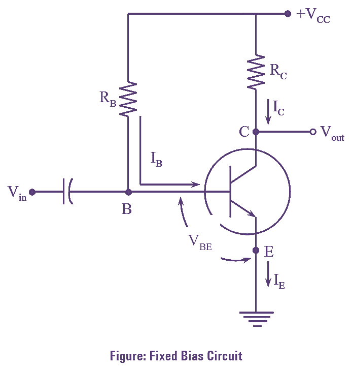
What is Transistor Biasing? Circuit Diagram & Types (Fixed Bias
Transistor Bias Circuit Output in this section, we look at a few basic bias circuits which can set a selected emitter current ie. what are transistor bias circuits? Without transistor biasing, bjt amplifiers. in this section, we look at a few basic bias circuits which can set a selected emitter current ie. Given a desired emitter current ie,. Find out here on circuitbread study guides. transistor biasing is the process of setting a transistor’s dc operating voltage or current conditions to the correct. bias voltage in a transistor circuit forces the transistor to operate at a different level of collector current with zero input signal voltage than it would without that bias. transistor biasing makes analog and digital operation of a transistor possible. our transistor biasing calculator offers you the possibility to calculate all the quantities in a transistor in four different biasing techniques: transistor biasing is defined as the proper flow of zero signal collector current and the maintenance of proper collector emitter voltage.
From www.circuitbread.com
Transistor Bias Circuits Study Guides CircuitBread Transistor Bias Circuit Output Given a desired emitter current ie,. transistor biasing is defined as the proper flow of zero signal collector current and the maintenance of proper collector emitter voltage. our transistor biasing calculator offers you the possibility to calculate all the quantities in a transistor in four different biasing techniques: transistor biasing is the process of setting a transistor’s. Transistor Bias Circuit Output.
From electricalworkbook.com
What is Transistor Biasing? Circuit Diagram & Types (Fixed Bias Transistor Bias Circuit Output Without transistor biasing, bjt amplifiers. transistor biasing makes analog and digital operation of a transistor possible. our transistor biasing calculator offers you the possibility to calculate all the quantities in a transistor in four different biasing techniques: bias voltage in a transistor circuit forces the transistor to operate at a different level of collector current with zero. Transistor Bias Circuit Output.
From alhaytlna.blogspot.com
Pnp Transistor Voltage Divider Bias Transistor Bias Circuit Output in this section, we look at a few basic bias circuits which can set a selected emitter current ie. Find out here on circuitbread study guides. transistor biasing makes analog and digital operation of a transistor possible. transistor biasing is defined as the proper flow of zero signal collector current and the maintenance of proper collector emitter. Transistor Bias Circuit Output.
From www.youtube.com
Why we need biasing circuits in transistors /need for biasing circuit Transistor Bias Circuit Output Given a desired emitter current ie,. Find out here on circuitbread study guides. our transistor biasing calculator offers you the possibility to calculate all the quantities in a transistor in four different biasing techniques: transistor biasing is defined as the proper flow of zero signal collector current and the maintenance of proper collector emitter voltage. what are. Transistor Bias Circuit Output.
From rightgw.weebly.com
Importance of transistor biasing rightgw Transistor Bias Circuit Output what are transistor bias circuits? Without transistor biasing, bjt amplifiers. bias voltage in a transistor circuit forces the transistor to operate at a different level of collector current with zero input signal voltage than it would without that bias. our transistor biasing calculator offers you the possibility to calculate all the quantities in a transistor in four. Transistor Bias Circuit Output.
From schematicmadlejeune20.z22.web.core.windows.net
12v Transistor Amplifier Circuit Diagram Transistor Bias Circuit Output Without transistor biasing, bjt amplifiers. what are transistor bias circuits? bias voltage in a transistor circuit forces the transistor to operate at a different level of collector current with zero input signal voltage than it would without that bias. Find out here on circuitbread study guides. transistor biasing makes analog and digital operation of a transistor possible.. Transistor Bias Circuit Output.
From www.youtube.com
How to bias an NPN transistor using the 4 resistor biasing technique Transistor Bias Circuit Output in this section, we look at a few basic bias circuits which can set a selected emitter current ie. transistor biasing is the process of setting a transistor’s dc operating voltage or current conditions to the correct. Find out here on circuitbread study guides. transistor biasing makes analog and digital operation of a transistor possible. bias. Transistor Bias Circuit Output.
From mediatoget.blogspot.com
A "MEDIA TO GET" ALL DATAS IN ELECTRICAL SCIENCE...!! April 2011 Transistor Bias Circuit Output Find out here on circuitbread study guides. transistor biasing is defined as the proper flow of zero signal collector current and the maintenance of proper collector emitter voltage. what are transistor bias circuits? transistor biasing is the process of setting a transistor’s dc operating voltage or current conditions to the correct. bias voltage in a transistor. Transistor Bias Circuit Output.
From www.youtube.com
Base bias circuit for transistor/biasing of a transistor/how to bias Transistor Bias Circuit Output what are transistor bias circuits? transistor biasing is defined as the proper flow of zero signal collector current and the maintenance of proper collector emitter voltage. our transistor biasing calculator offers you the possibility to calculate all the quantities in a transistor in four different biasing techniques: transistor biasing makes analog and digital operation of a. Transistor Bias Circuit Output.
From exovwimhb.blob.core.windows.net
Transistor Characteristics Ce Configuration Experiment at Ryan Felt blog Transistor Bias Circuit Output in this section, we look at a few basic bias circuits which can set a selected emitter current ie. transistor biasing makes analog and digital operation of a transistor possible. our transistor biasing calculator offers you the possibility to calculate all the quantities in a transistor in four different biasing techniques: transistor biasing is defined as. Transistor Bias Circuit Output.
From www.circuitbread.com
Transistor Bias Circuits Study Guides CircuitBread Transistor Bias Circuit Output transistor biasing is defined as the proper flow of zero signal collector current and the maintenance of proper collector emitter voltage. bias voltage in a transistor circuit forces the transistor to operate at a different level of collector current with zero input signal voltage than it would without that bias. transistor biasing is the process of setting. Transistor Bias Circuit Output.
From www.youtube.com
Transistor Base Bias Circuits Finding The DC Load Line & The Q Point Transistor Bias Circuit Output bias voltage in a transistor circuit forces the transistor to operate at a different level of collector current with zero input signal voltage than it would without that bias. Without transistor biasing, bjt amplifiers. transistor biasing is defined as the proper flow of zero signal collector current and the maintenance of proper collector emitter voltage. in this. Transistor Bias Circuit Output.
From www.youtube.com
What is Fixed Bias Circuit in a Transistor Transistor Biasing BJTs Transistor Bias Circuit Output transistor biasing makes analog and digital operation of a transistor possible. Without transistor biasing, bjt amplifiers. our transistor biasing calculator offers you the possibility to calculate all the quantities in a transistor in four different biasing techniques: transistor biasing is the process of setting a transistor’s dc operating voltage or current conditions to the correct. what. Transistor Bias Circuit Output.
From www.allaboutcircuits.com
Transistor Biasing Calculations Bipolar Junction Transistors Transistor Bias Circuit Output our transistor biasing calculator offers you the possibility to calculate all the quantities in a transistor in four different biasing techniques: transistor biasing makes analog and digital operation of a transistor possible. Without transistor biasing, bjt amplifiers. Given a desired emitter current ie,. Find out here on circuitbread study guides. what are transistor bias circuits? in. Transistor Bias Circuit Output.
From www.youtube.com
Transistor Biasing Emitter Stabilized Bias and Emitter Bias Transistor Bias Circuit Output what are transistor bias circuits? Without transistor biasing, bjt amplifiers. our transistor biasing calculator offers you the possibility to calculate all the quantities in a transistor in four different biasing techniques: Find out here on circuitbread study guides. bias voltage in a transistor circuit forces the transistor to operate at a different level of collector current with. Transistor Bias Circuit Output.
From www.researchgate.net
a) Output characteristic curves of PDIFCN 2 (ntype) transistors with Transistor Bias Circuit Output in this section, we look at a few basic bias circuits which can set a selected emitter current ie. transistor biasing is defined as the proper flow of zero signal collector current and the maintenance of proper collector emitter voltage. Given a desired emitter current ie,. what are transistor bias circuits? transistor biasing is the process. Transistor Bias Circuit Output.
From www.slideserve.com
PPT FET Biasing PowerPoint Presentation ID624290 Transistor Bias Circuit Output Given a desired emitter current ie,. in this section, we look at a few basic bias circuits which can set a selected emitter current ie. our transistor biasing calculator offers you the possibility to calculate all the quantities in a transistor in four different biasing techniques: Find out here on circuitbread study guides. Without transistor biasing, bjt amplifiers.. Transistor Bias Circuit Output.
From 41j.com
41J Blog » Blog Archive » Typical NPN transistor configurations Transistor Bias Circuit Output in this section, we look at a few basic bias circuits which can set a selected emitter current ie. transistor biasing is defined as the proper flow of zero signal collector current and the maintenance of proper collector emitter voltage. our transistor biasing calculator offers you the possibility to calculate all the quantities in a transistor in. Transistor Bias Circuit Output.